Monday, August 7, 2017

The End...???

That's All... For Now...

Today's the day I told myself would stop working on the framework, so that I must.  A lot got done in the past week that made me feel... somewhat satisfied with my work.  I managed to get skeletal animation working with a demo that shows off layered animations, or animation clip blending.  This post reviews the final week of back-end development... but that doesn't mean I won't be back with more!

Hierarchies & Poses

Nowhere in the animal3D framework is the word "skeleton" mentioned.  You're like, wait what?  I wanted to keep things as general as possible, so I called it what it is: a skeleton is a hierarchy.  Another common use for this is the scene graph, which is a misnomer because it's a tree.  The data structure I implemented goes off of Jason Gregory's implementation in Game Engine Architecture, where each node in the hierarchy can have a virtually infinite number of child nodes by storing them in an array that is ordered by "depth" in the tree.  However, in Gregory's implementation, the poses are stored with the nodes; I separated the two entirely.  The hierarchy part is nothing more than a collection of named nodes, and the poses are nothing more than a collection of poses.


What's a pose?  When we talk about a waypoint-based curve system, poses are the actual waypoints used to control curves.  Poses are usually broken down into "channels", which are individual spatial components of a 3D coordinate frame orientation: rotation, translation and scale, each broken down further by axis.  The screenshot here shows Maya's graph editor with a serious of waypoints on 6 different channel curves, the combination of which yields a single pose for the object being animated.  

These two features come together as what I call a "spatial hierarchy": a set-of-sets of poses that reference a hierarchy; really it's a giant matrix of poses, with one "row" per each node in a hierarchy.  Instead of having to set each pose for each node manually (which would absolutely suck), I implemented a HTR file format loader, which, in my opinion, is a very good format.  After this was done, I tested it by drawing a skeleton on the screen using each "column" of poses (one pose per node at the same index) as a known sample to display.


Getting this right actually took a long enough time.  I'd implemented HTR loaders before but I had forgotten the quirks of it; for example, to calculate the final local pose for each node (relative to its parent), rotations need to be stored as either matrices or quaternions and then concatenated with the base rotation, whereas for translation you just add the current pose with the base translation; my original guess was to generate a full transformation matrix for the base, one for each pose, and then concatenate to get the correct pose state.  Anyway, after local poses are calculated, the final step to seeing a living, breathing skeleton (oxy-moron, much) is this little thing called forward kinematics, where the world-space transformation of each joint is calculated by multiplying by its parent's world-space transform, the algorithm shown in the above screenshot (from my slides).  The root node's world-space transform is its local transform, but the rest of the joints only know how they are related to their parents; using logical inference, we can say that if we know how the parent relates to the world, and how a node relates to its parent, we therefore know how the node relates to the world.  The result of all this is a full skeletal pose.

Mesh Skinning


To see the process working with a 3D character mesh, I used the only rigged and skinned character I have in my possession, a four-armed dancing freak of nature (which I modeled, rigged, skinned and animated all by myself several years ago).  I loaded the mesh as an OBJ with skin weights, and implemented a vertex shader to skin the mesh.  The only real animation-related requirement here is that, on top of the world matrix from the forward kinematics algorithm, each node in the hierarchy must store an additional matrix: the inverse of the result of forward kinematics for the bind pose.  This matrix is then multiplied by the result of forward kinematics at any given time to produce the result.  The math is shown in this screenshot, also from my slides.  The logic: by taking the inverse of the bind pose world matrix, we're basically saying "go from the world pose at bind time to the local joint pose", then by multiplying this by the current world matrix, we are saying "now go to the current world state of the joint".  Ultimately, the skinning matrix is the "delta" transform from the bind pose to the current pose.

Animation Clips

When dealing keyframe-based animation, each frame can be treated as an "animation state" or "sample" in an animation.  A collection of samples can be called a "clip" or "sequence".  Usually, text-readable exported animation formats from programs such as Maya will contain every single sample as a keyframe instead of the curves used to produce these frames, which is fine, because part of the point of animation programming is to reproduce the effects these curves.  In any case, what these files don't mention is how the animator decided to divide up the timeline into clips or animation segments.  These can be the short frame sequences that we might watch and describe as "run", "walk" or "idle".  None of those are explicitly defined, you usually end up with a bunch of poses.  So, the animation clip utility serves to take said frames and organize them into segments with names such as "run", "walk" or "idle", which makes it easier to define a timeline for each clip.


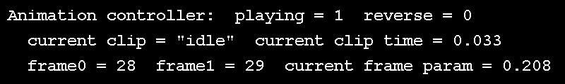
Wait, if keyframes are known, what about the unknowns?  If we have exactly 5 keyframes and we want to see them all at an even interval in 5 seconds, it's clear that we see one keyframe per second.  But does time move forward at a rate of 1 frame per second?  Probably not.  If we're running at 30 FPS, and we want our animation to be smooth, we need to see 30 frames, or samples per second; these are known as "in-betweens" or "samples", and the process of determining these is sometimes called "tweening".  This is achieved by using two of the known samples, we'll call the first one "key 0" and the second "key 1", and interpolating between them.  The in-between is controlled by an interpolation parameter, which is the relative time between the start and end of the current keyframe.  All of this interpolation parameter control is implemented in animal3D as an interface known as an "animation clip controller", which takes the current time and figures out where we are in a clip, describing our "key 0", "key 1" and the interpolation parameter between them.  This can be seen in action in the above GIF, rendered as a text overlay over the demo.

I spent a lot of time getting this just right because I knew it would be super useful with this next part...

Layered Animation & Blending


The cornerstone of any nutritious animation engine.  With all of the above utilities in place, I actually completed this in only a few hours.  The first part of this process is to have multiple instances of the animation clip controller running in tandem, each evaluating time for a different clip.  These can be thought of as individual timelines, or layers.  Each of the clip controllers provides the current and next pose indices ("pose 0" and "pose 1" respectively), so we know the two poses that we are blending between.  The clip controller is also responsible for calculating the interpolation parameter between the two frames; we'll call this the interpolation parameter alpha, "alpha" because it describes the first stage in the process: calculating the current state of the hierarchy for each clip.  I.e. we are not only blending between key frames; this stage helps us calculate in-betweens to blend.  We'll call the in-betweens "clip samples".  An illustration of this process is shown in the screenshot above.

There are three main blend operations that I explored here: 
  1. Scale: literally scales the effect of a clip sample pose by blending away from the base pose; an interpolation parameter of 0 yields the base pose, whereas 1 yields the input clip.  This behaves similarly to the alpha parameter, where "pose 0" is replaced with "base pose" or "bind pose".
  2. Blend/LERP: this is basically the LERP of animation blending: linearly interpolate from clip 0 to clip 1 using an interpolation parameter.
  3. Combine: this is commonly known as "additive" layering, where one clip happens and then the effect of another clip is stacked on top; basically you're combining the total effect of both inputs.  The scale operation is particularly useful 
The "scale" and "blend" behaviours have something in common: a secondary interpolation parameter that describes the relationship between inputs and outputs.  We'll call this interpolation parameter beta, which is the input to some interpolation algorithm using pre-interpolated inputs.  Where do beta parameters come from?  Whereas alpha parameters are "local" to animation clips, beta parameters are usually controlled by some factor in the simulation, such as player controls or environmental factors triggering a character to change animations.  The scale and blend operations can be seen in the GIF at the top of the post.  They produce the user-controlled output using this algorithm: 
  • The "idle" clip (breathing, arms lowered) plays on channel 0 (the first clip controller).
  • The "dance" clip (arms up, celebrating, it works, shit yeah) plays on channel 1.
  • The effect of "idle" is scaled by user input (e.g. joystick).
  • The effect of "dance" is scaled by a different user input.
  • The effects of both scaled clips are blended by a third user input.
Wouldn't it be nice if we had a data structure or algorithm to describe this process?  Luckily, we do.  The organization of all this is done by implementing an "implicit tree" structure, which is really just a list of which clips blend with which and what order; this is called a blend tree.  Each of the behaviours has a particular way to represent a node in a blend tree, called a blend node
  • Scale node: This diagram shows how the beta parameter is used to calculate the scaled clip pose, and how this translates into a blend node that would fit into a blend tree.  The node only has one clip sample input and a beta parameter to control the result.
  • Blend/LERP node: This works similarly to the alpha parameter, using pre-interpolated clip samples as the inputs, instead of keyframes.  This is effectively bilinear interpolation for poses.  The scale operation takes two clip samples and re-interpolates them together, using the secondary parameter, beta, to control the result.  In quaternion-based implementations, the SLERP (spherical linear interpolation) method is used to blend rotations, while translation can be controlled using normal LERP.
    •  
  • Combine/add node: This is another two-input node, but it does not involve interpolation.  The result is simply the effect of clip sample 0 followed by the effect of clip sample 1.  In some implementation, such as those that use matrices or quaternions, the order of inputs matters because a matrix/quaternion concatenation would be used; these are not commutative operations.
For all of the node diagrams, the "tree nodes" on the left are the input clips, after calculating the in-betweens using the alpha parameter, the operation in the middle is one of the three operations listed above, whose output is controlled using the respective beta interpolation parameter; the output is shown on the right.

Here is the blend tree representation of the process used to produce the GIF demo: 


The result?  Pure satisfaction.  But it gets better: I only named three blend nodes up there... but that's not all you can do with this system!

Until next time...

I think for 5 weeks worth of work I've done just enough to be ready for my classes, animation programming in particular.  I'm a little sad that I discovered so many flaws with the framework a couple weeks ago... and had the necessary urge to fix them all in a way that they'd never come back!  I am an engineer, after all.  If I could put one more week into this I would build some samples, but the one you see in the GIF at the top of this post is going to have to suffice.  Let it be an inspiration to the students: it looks simple, but read this blog over and you'll see what it actually takes to get that working from literally nothing.  That being said I'm pretty proud of what I've done to make animal3D into what it is.

Alas, the takeaways.  Did I learn from this?  Hell yes.  I've always had a knack for complex 3D math, and have been very familiar with its applications, but some of the things I implemented for this framework have been on the engineering wish list for years.  On top of that, one which I actually managed to complete is the art of the blend tree; before this I'd never actually programmed anything that went past the "alpha" interpolation phase.

What new things did I learn?  Hotloading is pretty useful.  Also, fun fact: I never bothered to try the "extern inline" combo in source code, which allows functions to be both compiled and inline, also super useful for dropping functions that should be .

What old things did I learn?  Does that even make sense?  Yes, I reinforced the fact that nothing will take the time originally estimated.  There will always be fine details overlooked that cause days worth of nightmares along the way.  I could go back in time through my repository commits and review all things that I should never do again... but in case I do these things again, I know why they occurred and how to fix them, which is quite possibly the most invaluable thing one could learn in the domain of programming hard skills.  Soft skills-wise, one needs to accept that real-time cannot be controlled, and shit happens.  But when you're an animation programmer, time is all you really have control over, so make use of it virtually.

I leave you with this picture of a cat-duck, because blending.  Thanks, internet.  And thanks for reading, see you again soon.


Monday, July 31, 2017

Almost There...


Demo Time

I really don't have much to say for this post.  Time is wearing down to the wire, and I've yet to come anywhere close to where I thought I'd be by now.  Nonetheless, here's a summary of my past week.

Wavefront OBJ File Loader

The cornerstone of any nutritious breakfast.  Want a model on the screen quickly?  Wavefront OBJ.  I wrote the loader using my existing geometry pipeline and it worked as expected.  The screenshot above shows the ubiquitous Utah teapot as a loaded OBJ; I plan to have this be the first "character" I animate.  Well, not really animate but... move.  Yes, since a good chunk of my material will be on locomotion, I need static objects that can move about using player control.  For the more advanced characters that may also need skinning, I added the option to add skin weights and bone indices to the OBJ-loaded mesh using Maya's XML weights format.  The loader just reads that file as well and stuffs weights and indices into the vertex buffer.  To top it all off, the loader will use the loaded model's positions, normals and texture coordinates to generate tangents and bitangents.

Geometry Asset Streaming

Since one of the main goals of this task list was to do some cool stuff for myself, this next bit was done just for fun.  I noticed that generating procedural geometry and loading OBJ files took several seconds, which is several seconds too many.  So I made a little system that allows for asset streaming: after an asset is loaded or created, it can be stored to either a binary file or simple byte array before being deleted.  The byte array method allows multiple data sets to be stored in the same stream, which can then be saved all at once to a file and loaded back in.  In the demo setup code, a file load is attempted first; if it is successful, the data is read directly from the file; otherwise, the data is created from scratch and then saved for the next run.  It's quite handy because load times go from several seconds to maybe a tenth to a quarter of a second, which is barely noticeable.

The Demos Begin

I have managed to start working on the animation samples, luckily.  So far I have a custom format for storing animation clip information that can be loaded in.  Right now I'm building a "keyframe controller" that will basically behave as an "animation player" or "channel" so that future static keyframe or blended frame tasks become super quick and easy.  Considering I want to do things like skeletal animation blending, this will help with the notion of frame blending and, later, blend trees.  I figure I'll start off with something that uses static keyframes, but still requires some sort of time controller: sprites.  I have some test sprite sheets for this reason, and have decked out a sample keyframes file to organize its frames.  Rendering sprites will be next up.

One more week...

Like I said, not much to discuss.  Sorry this one is not as juicy as the last post... maybe all the stuff that happened that week is why I consider myself behind this week... oh well, it is what it is, and at least I'll have something usable for the course.  Hopefully by the next (and final) post I will have at least one kick-ass demo of something advanced to show.  I'm hoping for IK.  But until then...

Monday, July 24, 2017

So Much More than "Just Data"

"It's just data."

Any student I've ever taught has heard me say these words.  Most times in this order, sometimes not, just to mess with them.  But it's true: when dealing with graphics, animation, any kind of memory... you really need to know what it is you're dealing with it, where it lives and how you deal with it.  This post discusses my week struggling to build procedural geometry and a couple takeaways.

TL;WR: 

Always remember, kids: sharing is caring, but don't forget to mind the implications of the data you're using: where is it stored and how many bytes!

The Purpose

Since it's about prototyping animation algorithms and not so much about the finished product, the intent behind adding procedural geometry to the mix was to be able to generate meshes that resemble animate body parts or bounding boxes.  I feel as though skipping to the OBJ or FBX loader would distract my students from the point of development, which is, again, the algorithms, not making everything look pretty.  Of course, we may need high quality loadable meshes later on to make what we do believable, but to start I just wanted something "simple" and 100% programmer accessible.  The course I'll be using this framework for assumes that the 3D modelers and animators are doing their job elsewhere, and it is up to the students --the programmers --to provide them with an environment in which they can bring life to their subjects.

Thus, I took it upon myself to produce a set of algorithms that would generate 2D and 3D primitives with programmer-defined parameters.  For example, you want a full-screen quad?  Go and make yourself a 2x2 procedural plane with texture coordinates!  You want something that looks like a bone for a skeleton?  An elongated wireframe pyramid should do the trick!  How 'bout a big ol' shiny sphere?  Tell it the radius, slices and stacks, and you're golden.  Etc.  This way we're generating prototyping primitives quickly without needing to worry about finding free models that are perfect for the framework or actually modeling things.  That being said, I did not expect to spend an entire week on geometry, but it was fun so well worth it.  I hope my students appreciate the hours I put in so they won't have to... seriously.

The Outcome

My original system design was to pass a pointer to a VAO, VBO and IBO to 14 different generator functions.  Then I remembered I'm a modularity freak and this would not be good for reusable primitives and sharing buffers.  So I simplified the system: 
  • Procedural Geometry Descriptor: a shape-agnostic data structure that holds "shape parameters" (see descriptions below) and "flags" (see next bullet), a vertex and index descriptor, and the vertex and index counts.
  • Flags: different options that one can set to help with generation: 
    • Axis: the option to change the default orientation of the shape; the default for 2D shapes is to have the normals point along +Z, for 3D the axis is also +Z.
    • Attribute options
      • "Vanilla" mode: enables vertex positions, and indices for shapes that need them.  Simple, small, efficient.
      • Wireframe: the shape produced will be made of lines instead of solid, positions and indices only to keep it ultra simple.  This option also removes the diagonal lines that cut across rectangular faces.
      • Texture coordinates: enables UVs for the shape.
      • Normals: enables vertex normals for the shape.
      • Tangents: the generation algorithm will calculate and store a tangent basis for every vertex; this option automatically enables texture coordinates and normals, since normals are part of the basis and "tangent space" is actually a fancy name for "texture space", or the 2D space that is UV land.  If you didn't already know that, now you do.
        • Also (and this is super important) a tangent is indeed tangential to the surface in 3D, but it only describes one basis vector; tangent is along the surface, normals point away from the surface... but what's the third?  Just want everybody to know that this is called a "bitangent" when dealing with a 3D surface, because it is a) secondary (hence, 'bi') and b) tangential to the surface, instead of pointing away from it like a normal.  For a line or curve, the equivalent basis vector is known as a "binormal" because it shares the "point away" behaviour or a normal.  I often hear the two terms being used interchangeably but this drives me nuts because they are different things in different contexts.  Students if you're reading this I will dock you points if you mix these up.  Argh.  End rant.
Along with these options, the user calls a "descriptor setter" for a given shape type, since they all have different parameters.  All setters take a pointer to a descriptor, flag and axis, and the following shape-specific parameters: 
  • Triangle: nothing special, ultimately a hard-coded data example to prove that the geometry system is alive.
  • Circle: input a radius, number of slices (divisions around the axis), and radial subdivisions (divisions away from the axis), and you get a circle.
  • Plane: width, height, and subdivisions for each.  'Nuff said.
  • Pyramid: Base width (square) and height.
  • Octahedron: A double-pointed pyramid, base width and total length.
  • Box: 3D box that doesn't ask for axes, but you specify the width, height and depth, and subdivisions for each.
  • Semisphere (or hemisphere, whatever): radius, slices, stacks (divisions along axis), base divisions (circle divisions).
  • Cone: ditto.  Side note, what I love about this shape is that it has the exact same topology as a semisphere, so once I had that done, this was super easy, just using a different algorithm to position the vertices.
  • Sphere: radius, slices, stacks.
  • Diamond: ditto, also same idea as cone, but there is an extra ring at the center because the normals switch from directions instantaneously instead of smoothly.
  • Cylinder: radius, slices, body divisions and cap divisions.
  • Capsule: ditto.  What I love about this one is that, even though people think it's so crazy, it has literally the exact same topology as a sphere; the only difference is that the body vertices and normals are prepared using the cylinder's algorithm.  I thought this one would take me forever but I completed it faster than any of the other shapes.  Maybe that's because all the bugs had been destroyed by this time?
  • Torus (coming soon): in simple terms, a donut.  Major radius describes the size of the ring itself, while minor radius describes the thickness of the ring.
  • Axes (coming soon): a helpful coordinate axis model.
The actual generation of renderable data is done by first creating a VAO to represent a primitive's vertex descriptor, then passing a descriptor to one "generate" function, which calls the appropriate procedural generation algorithm.

All of the currently-available shapes can be seen in the GIF at the top of this post, but there are a couple unimplemented for the moment.  Like I said, I didn't expect to spend this long on procedural, but hey, I'm learning and stomping out flaws as I go.

The Struggles

I am very happy about this undertaking because, as you know from last week, up until this I had a bunch of untested graphics utilities.  Procedural geometry, in my opinion, is the ultimate stress test; I think I've seen just about every fatal flaw with my existing utilities.  Here I'll discuss three of them that drove me absolutely batshit insane.  We're talkin' 4am nights of "I've almost got it... nope there's another thing..."

The whole thing about putting together renderable primitives is that they are made of vertices, and vertices are made of attributes, and attributes have elements, and an element has a byte size, and all of this comes together to occupy some block of memory... but in order to draw a primitive, even just a single triangle, OpenGL needs to be told all of this information, therefore you need to know it.  If you're a memory freak like me, you'll want to know the address of every damn byte you use.  This process becomes particularly difficult when dealing with the GPU, since it's harder to actually see the data (although modern IDE's have some graphics debugging tools), so when something goes utterly wrong one can only scrutinize the code until something jumps out as unfamiliar.

Here are the three main discoveries that I really learned from while creating procedural geometry.

1. Modularity

Figure 1: The two steps to generating a wireframe sphere: 
a) rings perpendicular to the body; 
b) spokes parallel to the body
This one is not so much a bug but more of a takeaway. About halfway through the implementation of the cone I realized that I was "reinventing the wheel" (heh) to get the base geometry.  I said, "It's a circle, I have a circle already, why not integrate that?"  So that is what I did: converted the circle generator into a publicly accessible algorithm so that other primitives could use it to make my life easier as a programmer (can't emphasize that enough).  I consider it a wise investment, since said circle is now used for the circle geometry itself, the base of the cone, the base of the semisphere, and the two caps of the cylinder.  In addition to creating algorithms that prepare the physical geometry, I realized that I should do the same to create indices for shapes that have similar topology; for example, to create a wireframe sphere, one must first draw the lines that make up the body, then draw "spokes" that extend from cap to cap, all without creating any duplicate vertices or cutting the line strip.  This exact principle also applies to the cone, diamond, semisphere, cylinder, and capsule, and soon to be torus.  This process is illustrated in Figure 1... yes I'm using figures now, it's easier.  Obviously, writing a single robust algorithm that handles all of these cases is the most engineer thing one could do.  So I did.

2. Mind the Gap

This one took me an entire day to track, I was very tired and sad.  At the end of the day I had a very unlucky situation that actually ended in me being thankful that it occurred.

As I may have mentioned in a previous post, I fully intended for OpenGL buffer objects to contain whatever data the programmer wants, to save both space and keep everything contiguous.  This ultimately has two implications: 
Figure 2: A buffer that stores 3 different kinds of 
vertices, each described by a VAO.
  1. Multiple vertex formats can be stored in the same buffer, whether you're building geometry primitives that have the same attribute arrangement or different (I call these arrangements "vertex formats").  Recall that a VBO is agnostic to what it contains, while the VAO minds the data and what it represents, i.e. where to find the start of a vertex attribute in a sea of bytes.  So, you can have one VBO and two VAOs that describe what it contains and where.  See Figure 2 for an example of this.
  2. Figure 3: A buffer that contains both vertex attribute 
    and index data for a model.
  3. Index data coexisting with vertex data: on top of attributes; a block of index data could be stored either before or after the index data; it's important to be sure that a VAO describing vertex data after index data uses the appropriate offset.  Figure 3 illustrates a buffer that contains both vertex and index data.
Seems pretty logical, right?  What I attempted while building all of these primitives was taking these two principles and smashing them together.  Here's the story: 

Figure 4: Ohgawdwhy.
I discovered this bug while implementing the octahedron, which I started after implementing the pyramid.  For some bizarre and sadistic reason, while my solid octahedron was perfect, the wireframe one was true nightmare fuel.  See Figure 4 for an approximate illustration.  The pyramid was fine in both modes, but the octahedron just could not even.  Naturally I investigated...

...and suddenly it was 1:00 AM.  Now, I'm not usually one to throw my hands up in the air but I did exactly that and said, "I am le tired."  So, since there are no buses running at this hour, I decided to walk home and take the time to clear my head.  This trek takes about 35 mins.  So I'm walking and thinking about this issue, nothing.

Now, my apartment uses key cards to open the doors instead of physical keys, which was kinda novel at first but I prefer hardware.  It also makes me anxious every damn day because you never know when electronics will fail.  Trust me, I'm a graphics programmer.  Anyway, my worst fear came to fruition at 1:35 AM when I took my key out and swiped it.  As my first instinct is to push and move forward, I ended up faceplanting the door as it did not open.  I tried again.  And again.  And again... Well, shit.  For my reaction, please see Figure 4 again.

Lucky for me, I have a spare key, which I keep at the office.  To make things worse, for some reason at that moment, my phone decided it would not cooperate for any reason.  So I said, "Welp, I guess I'm walking back."  I retrieved the key at 2:10 AM and fought the urge to keep pressing at the mysterious octahedron.  I defeated the urge and left for home.  During my second walk home I had the following train of thought: 

The thing about the octahedron is, when it's solid, all of the vertices are different, even if they share the same positions, because the other attributes are different.  One thing to understand about indexing is that it should only be used if indices refer to a set of the exact same vertex multiple times, i.e. the exact same combinations of positions, normals, UVs, etc. occur repeatedly.  Since a solid octahedron vertices are all different, I decided not to use indexing.  However, for a wire octahedron , most of the vertices are used at least twice to produce a line-strip that forms a octahedron shape.  Since the only attribute I use for wireframe is position, a duplicate position means a duplicate vertex, so indexing is more than appropriate.

Figure 5: Bad buffer architecture: Index data for the first 
model is wedged between two vertex sets; indices for the 
second model make no sense.
The kicker: all of the previous shapes have the same number of indices for solid and wireframe mode, but suddenly here's Mr. Octahedron, who has zero indices for solid and 12 for wireframe.  I realized that in exercising both storage principles discussed above I had created a buffer with multiple vertex formats and index data, with indices immediately following vertex data, then more vertex data after that.  Figure 5 shows an example of this scenario, with the problem explicitly marked with a big X: the indices used for the wire octahedron were pointing at index data for the previous shape, not its own vertex data as expected.  Alas, this makes sense if the vertex and index data are wildly interleaved.  Thus, the indices for Mr. Octahedron were telling the VAO to use someone else's index data as if it were vertices, so the monstrosity from Figure 4 came into existence.

Figure 6: The correct buffer architecture: All of the vertex
data is grouped together at the start of the buffer (could also
be a mix of vertex formats), and the indices refer to the
correct vertex data.
I realized that the desired result would require re-evaluation of how my primitives stored their data within the provided buffer.  Since stuffing it all right at the end produces an unwanted gap in vertex data, I would need some sort of barrier that explicitly separates all vertex data from all index data, seen in Figure 6.

The solution: the general data structure that I use for buffers now has a "split" index: the limit for occupancy in the first half of the buffer, used for one grouping of data; anything after that byte is used for a different grouping of data.  So now it can be used to explicitly separate vertex data of mixed types (again, the VAO distinguishes formats, so I don't need dividers for this).  The procedural generator function knows that vertices should be stored in the first half of the buffer, while indices should be stored after the divider.  Piece of cake.

I made it home at 2:45 AM.  Would my key work?  Yes.  Now I had to fight the urge to go back to work and fix the bug.  But we all know that a "quick fix" that "should only take a couple of minutes" is usually deceptive, which it was.  The octahedron cost me two days before I finally achieved the solution described above.  Now then...

3. Size Matters

With a solution to problem #2 in place, here's another juicy graphics engineering problem.  I mentioned that a wire octahedron requires 6 unique vertices; it's one of the most basic shapes.  Let's add a circle to the mix with 16 slices and 4 subdivisions, so we have 65 more unique vertices.  How about a sphere with 16 slices and 12 stacks?  This shape has 219 unique vertices.

Figure 7: When indices are larger than the maximum
allowed by their data type, they will roll over to zero
and your shape will be drawn using vertices from who-
knows-where in the vertex set.
What do all of these numbers have in common?  Well, each one is less than 256, so on their own we would be able to store their indices as unsigned chars (single bytes).  The problem arises when storing multiple models' data in the same buffer.  If the above octahedron, circle and sphere all live in the same buffer and have exactly the same attributes enabled, then they share a common format and VAO, which means the "base vertex" for the next shape should accumulate how many vertices have been stored before it.  If the octahedron was stored first, the index of its first vertex would be 0, the circle's first vertex would be at index 6, and the sphere's base index would be 71... but what about the next shape?  We add 219 and suddenly the next shape to be stored has a base index of 290.  While the individual shapes could use bytes to store their indices, as soon as they are sharing a buffer, half of the sphere described above and the entirety of the next shape would be messed up.  Figure 7 shows what happens when your maximum index exceeds the maximum allowed by the storage type.  Naturally, I learned this the hard way; please refer to Figure 4 once more for what I saw.

If we use indices to draw instead of storing repeated vertices, we must consider the total number of vertices because it would otherwise be incredibly difficult to determine which primitive starts at which address.  Therefore, my solution to the problem was to implement a "common index format" that is shared for all primitives using the same VAO.  The algorithm for preparing geometry is as follows: 
  • Create shape descriptors
  • Add up the total number of vertices using the common vertex format
  • Create common index format given total number of vertices
  • Add up the space required to store vertices using the common vertex format (A)
  • Add up the space required to store indices using the common index format (B)
  • Generate "split" buffer with A bytes for vertices and B bytes for indices
  • Generate VAO for common vertex format
  • Generate all renderables
When calling the "generate" function, the programmer passes a "base vertex" number, which changes the first index from 0 to however many vertices represented by the current VAO are stored in the buffer before the current shape.  There is also an optional parameter, a pointer to a "common index format" that should be provided for drawables sharing a buffer with others; otherwise the generator will defer to the shape's own maximum index to decide how much space it needs.

This algorithm seems tricky but I think it's well worth it taking the time and care to produce a shared buffer that is rather self-sufficient; you allocate some space and the procedural shapes just know what to do with it.

TL;DR: 

Always remember, kids: sharing is caring, but don't forget to mind the implications of the data you're using: where is it stored and how many bytes!

Demo time...

With geometry [almost] out of the way, I should now be able to prototype my own animation algorithms for the class.  Inspiration for the students, if you will.  I sincerely hope that the number of bugs I experience in the future will be minimal, now that I've caught and fixed pretty much everything that could have gone very wrong graphics-wise.  I only have two weeks left in the time I originally challenged myself to complete everything in, so I'm somewhat hopeful that I'll have enough to go on.  For the amount of work I put in, I damn well better.

Until next time, remember to respect your data.

Monday, July 17, 2017

Graphics, Graphics, GRAPHICS!!!

Another Week and a Whole Lot of Graphics

I'll keep this one short otherwise I'll go on about graphics forever.  Long story short, I implemented a bunch of graphics features to make prototyping easy.  Tested the hell out of them too.  Also, most importantly, I learned a thing or two along the way.

Graphics Features

A summary of the things implemented: 
  • Shader and program management
  • Vertex and index buffering
  • Vertex array object
  • Textures
  • Framebuffer objects
  • Started procedural geometry

The Prelude: Immediate Mode

For people new to OpenGL, "immediate mode" rendering is when vertex attributes, such as color, texture coordinates, normals, and the position of a vertex itself, are sent to the GPU one at a time as needed, wait in the pipeline until a primitive forms, become part of the primitive drawn, and get discarded immediately.  Hence, immediate mode refers to how data is used and forgotten about immediately.  This was what I used to test my window's drawing abilities.  Despite it being terrible, it's great for short-term debugging.

With a simple triangle on the screen (not the one you see above, I'll get to that), I decided to write shader and shader program wrappers to test the programmable pipeline, the staple of any modern rendering framework.  With immediate mode attributes flowing through the pipeline, it was very easy to see what effect my shaders would have on them... and that the wrappers were working.  That being said, immediate mode needed to go...

Vertex Drawing

Enter "retained mode": instead of data being immediately used and discarded, modern geometry is typically stored in what's called a "vertex buffer object" (VBO) that lives in a persistent state on the GPU (the rendering context).  VBOs contain vertex data for a primitive as a collection of attributes.  I implemented a wrapper for this as well.

You're probably wondering, "But Dan, what if you have a lot of repeated vertices, doesn't that take up a lot of redundant space?"  I thought of that too.  For this we have another kind of buffer called either an "index buffer object" (IBO) or "element buffer object" (EBO).  This stores only a list of indices that describes the order in which OpenGL should select vertices from the VBO to send down the pipeline.  It's very useful for geometry with many repeating vertices.  Let's say we have a vertex with 8 floats, or 32 bytes, that is repeated 6 times; a non-indexed vertex buffer would need 6 copies of that vertex, so that's 192 bytes.  Alternatively, the single vertex could be stored in a vertex buffer, with the integer index of said vertex occurring in an EBO 6 times, which is only 24 bytes.  Yes, I implemented a wrapper for this as well.

Now you're probably wondering, "Dan, how does OpenGL know where the attributes are in the buffer if you're not explicitly telling it like immediate mode does?"  Well, for this there is a handy thing called a "vertex array object" (VAO), whose job it is to describe everything about data in a vertex buffer.  The offset in the buffer, the size of each attribute, how many elements, everything you'd need to know when drawing a primitive!  A VAO saves the state of a vertex buffer that it describes (and an index buffer if one is used), so when you want to draw something, you just have to turn on the VAO and say "draw" with how many vertices are being drawn.

All of these are part of what I call a "vertex drawable", which is basically a little structure that knows which VBO, EBO and VAO it uses for drawing.  But the buck doesn't stop there, oh no.  Your next question might be, "Dan, do you have a unique VBO, EBO and VAO for every object in the scene?"  Absolutely not!  The great thing about all these is that you can share buffers for data belonging to different primitives.  For this reason I created a "buffer" interface that helps keep track of the data stored; when a chunk of data is sent to a buffer with a specified size, the interface spits out the offset to that data, so you know where it begins in the buffer.  For a shared vertex buffer, you can use a new offset to new attribute data in the buffer to describe a new vertex type in a new VAO that points to the same buffer.  In other words, as long as you know where data for a vertex primitive begins in a buffer, you can stuff many different primitives' data in that buffer.  You can also use the same buffer for index data, you just need to know the offset to that as well.

Textures & Framebuffer Objects

This was more for completion if anything, I didn't really need these wrappers.  I just decided to write a wrapper for texture creation, either from raw user data or from a file (using DevIL).  It wasn't a bad idea because I realized I might actually want textured objects.

I also made a wrapper for framebuffer objects (FBO) so that it is possible to do offscreen rendering.  This may be useful for people writing debugging tools that should be overlaid on the main scene image.  Multiple render targets enabled, all the fun stuff.  But to make things interesting, I also implemented a "double FBO" which is basically an offscreen double buffer.  It has a swap function so that the back buffer's targets are used for drawing while the front buffer's targets can be sampled.  This could be incredibly useful for an algorithm with many passes, such as bloom, because instead of creating and having to manage two separate FBOs for alternating passes, just create one double FBO and have it manage the data flow.

Reference-Counting Graphics Handles

Another thing I cooked up to help manage all of the above madness is a reference-counting handle object.  Anything with an OpenGL handle has one of these, and whenever something references an object with an OpenGL handle, a counter is incremented.  When one of these resources should be freed, you call "release" and the counter decrements.  When the counter hits zero, the appropriate release function is called.

Now I've always heard people say "be careful with function pointers" but I never really had any problems with them... until now.  The aforementioned "appropriate release function" is just a pointer to a facade function that simply calls the appropriate OpenGL release function, or functions if the object has multiple OpenGL handles associated with it.  What I didn't realize, however, is that hotloading the demo results in these functions' addresses going "out of scope", resulting in dangling pointers.  I was confused the first time I experienced this: I was telling a graphics object to release, and it should have just destroyed the object, but instead the program would just jump to a random line of code.  This was especially confusing with breakpoints set because you'd be on one one line and suddenly in a different file.  When I realized the problem, it made perfect sense: the command in assembly would be exactly the same as it was before hotloading, "jump to 0xWhatever", so without actually changing the value of 0xWhatever you could jump anywhere.

Two possible fixes: either destroy and reload all graphics objects, which I did not want to do (as it would defeat the purpose of hotloading, why not just close and reload at that point); or reassign these function pointers.  I chose the latter, and wrote an "update release callback" function for anything that has a graphics handle.  All it does is change the value of the release function pointer.  Problem solved, but at the same time I now see the real reason why function pointers can be a pain in the ass: the function moves.  Tricky functions, you.

A Blast from the Past

Alas, the explanation of the incredibly beautiful triangle you see above.  For me personally, seeing the triangle on-screen was very thought provoking: it heavily resembles the very first image I ever saw of shaders in action.  That was back in second year of undergrad in an intro graphics course.  Shaders were mentioned and described in minimal detail for no more than 10 minutes, with a screenshot to accompany, much like the one above.  And that was the last formal curriculum I had on shaders; all of the stuff I've done has been self-taught.  There was one lesson two years later when the TA of a totally non-graphics course took over lecture while the prof was away to teach our cohort about shaders, but by then it was clear I was the only one in the room (aside from the TA) who knew a single thing about this stuff.  Ah yes, I remember this moment clearly, and I'll happily boast about it.  At the same time everyone else was learning how to multiply matrices in a vertex shader, I was watching a 3D animated character I made (the 4-armed moldy orange... you'll see him later) dance around the screen with dual quaternion skinning and tangents displayed.  I was sitting at the front of the class, off to one side.  I doubt the guy next to me was listening to the TA.

And yet, at the top of this post, all you see is that damn triangle.  If I had been told that day about the work that goes into producing a triangle, *properly* mind you, I might have noped right the hell away from graphics forever.  But I endured, and the triangle you see uses a shared vertex/element buffer with a VAO to describe the vertices and a shader program to display any of the attributes in the primitive.  It is proper evidence that every single piece of my framework is alive and well, and more importantly, alive and well simultaneously and harmoniously.

What people don't realize about graphics, and animation for that matter (since both are very heavily algorithm-oriented) is that every step must be carefully traced, and to get a measly triangle on the screen requires a ton of prep followed by a single draw call.  And that's exactly what this is.  There is a story that I heard long ago (can't remember where) about a company whose first bout with programming for the PS3 was to spend far too many days getting a "black triangle" on the screen.  As soon as it appeared, they all threw their hands up, abandoned their post and went out drinking.  I greatly appreciate this, however this is not my first triangle, and to me it was a simple reminder of "Damn, I've come this far, might as well keep going."

Until next time...

I apologize for the lack of imagery in this post, the most interesting thing I have to test all of this is the triangle.  Soon I'll have demos that actually have things going on in them, so there will be stuff to show.

Next up: finishing procedural geometry and an OBJ loader!

Monday, July 10, 2017

The First Week


One week...

...and a surprising amount of productivity.

I feel like it's been forever since the first post when I actually decided to commit to the project.  Nonetheless, I've begun coding like a crazy person and got pretty far for a week.  In this post I'll discuss the architecture of the animal3D framework and the features that I've implemented so far.  Don't expect any fancy diagrams, you'll get screenshots at least.

Framework & Pipeline Architecture

First, I should mention that I was debating building animal3D for both Windows (Visual Studio) and Mac (Xcode).  Given the time constraints, I decided to stick with Windows for the time being, since that's what my students and I will be using approximately 100% of the time.

That being said, I began with a new solution in Visual Studio 2015 (I like to stay one version behind for compatibility), to which I added 3 projects: 
  1. Static library animal3D.lib, which is where all of the built-in graphics and animation utilities will live; 
  2. Dynamic library animal3D-DemoProject.dll, which is where actual demo code will be developed (e.g. a game or animation concept demo); and 
  3. Win32 application animal3D-LaunchApp.exe, which is the actual windowed application that renders the active demo.
The static library is linked to the dynamic library, which, when compiled, behaves as a free-floating "package" that can be hot-reloaded into the window at run-time.

Windowing & Hot Reloading

I've been interested in learning how hot reloading works for a long time, so this was a perfect opportunity to explore.  I must say, I figured it out faster than I thought I would, and it's super useful.  In short, hot reloading (a.k.a. hot swapping or code injection) is when code is recompiled and linked while an application is still running, thus changing the behavior of the app in real-time.  Unreal Engine and Unity3D are prime examples of engines with this feature.  With this implemented in a C-based framework, the C language effectively becomes a scripting language, only requiring a few seconds to rebuild and inject new code into a running app.

Windowing

My first task was to get a window on the screen.  One of my initial visions for the framework was to not use any other frameworks, so I did this from scratch.  I dove back into one of my older frameworks in C++ and translated its windowing classes into function-based C.  Just regular old Win32 programming.  The result was a window with an OpenGL rendering context and a menu.  There is also a console window so printf can be used.  All of this is implemented as "platform-specific" code in the launcher app project.

The menu is very small and used strictly for debugging.  I tried making a dialog box from scratch but that proved to be overly-complicated.  Besides, a window menu is directly integrated in the window and is always there in case the user wants to change something.  The above screenshot shows all of the window's options: load one of the available pre-compiled demo DLLs (hot loadable but not debuggable); shutdown and immediately reload the current demo; hot load the debuggable demo project DLL with an update build or full rebuild; reload the menu (in case new demo DLLs appear); and exit the current demo or app all together.  Exiting can be programmed into a demo, i.e. using an exit button or a quit key press; this is explained briefly below.

The important thing to note about windowing in Win32 is that there is a "message loop" or "event loop" in which messages from the window are processed.  Messages that should be responded to in some way call external functions, known as callbacks, which give the client a chance to respond to an event, such as a key press or the window being resized.  The demo project is entirely responsible for handling its own callbacks; this is described next.

Demo Information


When the 'load,' 'build and hotload' buttons are used, the first thing that happens is that a text file is loaded.  This text file explains the callbacks that the demo has available, and the name of the function that should be called when a particular callback occurs.  This screenshot shows an example.  Long story short: the name of the demo, the DLL to load, the number of callbacks implemented, and the list of named callbacks with a pre-defined "hook" function that the callback represents.  For example, this screenshot says that a function called "a3test_load" should be used when the 'load' event is triggered, "a3test_unload" should be called when the 'unload' event is triggered, etc.  It's an easy, scriptable way for users to be able to write their own callback functions and tell animal3D which one maps to which callback.  Documentation is provided with the framework that explains how to write the file and what the callbacks should have for their return types and arguments.  The next section explains how this is actually used.

Hot Reload

Believe it or not, this part is actually simpler than it sounds.  After reading a description of the demo to be loaded, the application loads the specified dynamic library (DLL) into process memory and links its functions using function pointers.  Before this happens, the window callbacks just point to dummy functions, but all that changes once the library is loaded is that the window will call user-defined functions.  I also wrote a batch script to run Visual Studio's build tool when this happens so that one could also change the code and re-compile without having to close the window.  The gif at the top of the page shows this in action: the window starts off rendering a black-to-white pulse effect, the user selects the hot reload option from the menu, and after a few seconds the window starts rendering a sweet rainbow.

One might ask, "But Dan, can I still debug my demo after hot loading?"  Yes, thankfully.  One of the main struggles with creating this feature was that Visual Studio locks all PDB files, including those of dynamically-loaded modules, as long as the process is being debugged... even if a module has been released.  To "fix" this, there is an option in Visual Studio's global debugging settings called "Use Native Compatibility Mode" which one must check to bring the debugging format back in time a few years, thereby magically allowing PDBs to be freed when their respective module is released (found out about this here).  I had conceived an over-complicated naming system, but at the end of the day there were still piles of PDBs being activated and locked, which triggered me a little bit.  As long as I have my breakpoints working after reloading, I'm happy!

Pipeline Summary

Long story short, with animal3D you're given a "standardized" render window whose job is to call upon a user-built DLL to do the real-time tasks.  The programmer just fills in a bunch of named callbacks in the DLL, writes up a line of text describing said callbacks, and lets the window figure out the rest.  The whole point of this was to a) get some basic rendering working, and b) streamline development without having to continuously restart the app to change something.

Additional Features

All of the above describes the architecture of and relationship between the dynamic library and the windowing application.  The static library has a few features of its own to start: 
  • Keyboard and mouse input: 
    • Ah yes, the classics.  I built simple state trackers for the keyboard and mouse, which can be modified in the respective callbacks and queried in other functions.
  • Xbox 360 controller input: 
    • A wrapper for XInput so that controllers will work, and states can be tracked and queried with ease.  I deemed this as a priority because, eventually, animation should be controlled using a joystick.  What better way to show off transitioning between walking and running, jumping, attacking, etc.
  • Text rendering: 
    • Simple text drawing within the window for a basic real-time HUD instead of having to rely on the console window.
  • Threading: 
    • A basic thread launcher function and thread descriptor.  The user passes a function pointer and some arguments, which get transformed into a thread.  Animation tasks may be delegated to a separate thread from rendering... which may also have a thread of its own!  An example of threading can be seen in the gif above: the text spewing out to the console is a threaded function in action.
  • High-precision timer: 
    • The cornerstone of any renderer: a decent frame rate.  Here it's as simple as starting a timer with a desired update rate and updating it every time the idle function is called; if it ticks, it's time to do a render.
  • File loading: 
    • A very simple wrapper for reading a file and storing the contents as a string.  This will come in handy for loading things like... shaders!

On to the next round...

Next up: rendering utilities, so that demos can actually be interesting and have stuff showing up.
  • Shaders
  • Vertex buffers and arrays
  • Framebuffers (why not)
  • Textures
  • Procedural geometry
If I can get through all of these this week, I'll be super happy and farther ahead than I expected to be at this point.  I expect to be working on the actual animation demos a couple weeks from now.

Until next time... I'll be programming like an animal!

Thursday, June 15, 2017

animal3D: Minimal 3D Animation Framework

minimal + animation = animal

I am ashamed to say that I have never written a development blog before.  The fact that I consider myself a game engine programmer makes this even more shocking.  For the past 5 years I have written about one framework per year, with purposes ranging from 3D math, to 3D graphics, to teaching tools.
This summer I am preparing to build yet another custom game development framework, with the primary purpose of giving my students support and a solid starting point for my upcoming course, Advanced Animation Programming.  After much internal deliberation and several Google searches, I have decided on the name animal3D, which is a portmanteau of "minimal" and "animal" (and sounds kinda cool).  I even went as far as making a logo!
I envision something that C/C++ programmers would want to use to prototype and build data structures and algorithms for 2D and 3D computer animation.  It sounds complex, but I want to try to keep it simple (stupid), hence the minimal bit.  I am allotting myself exactly 5 weeks, starting in July, to build enough 3D graphics utilities to facilitate rapid development of 3D animation algorithms using the C programming language.  I don't expect a full-fledged game engine, just enough to build demos and teach my students some animation programming.  The teaching part is key; naturally it will not be feature-complete, but that doesn't mean it won't ever be.

Animation Programming

This has been one of my core interests since I first learned what it was.  In my course I am to teach traditional 2D and 3D animation algorithms and techniques, such as sprites, forward kinematics, speed control, animation blending and more.  Some of the advanced topics will include inverse kinematics, tuning animation and locomotion, layers and whatever else I can think of.  I also plan on delving into the mathematics required in the field, namely the quaternions, which I have heard are in high demand these days, and I happen to know quite a bit about.  I am still toying around with the course design itself, but I'll be sure to share when I figure it out.

Graphics & Other Utilities

Since animation and graphics are so heavily intertwined, I plan to build some core graphics and application tools so that development using animal3D can be mostly focused on the animation part.  Some of the things on my current to-do list are procedural geometry, windowing, high-precision timing and threading, all from scratch.

To be continued...

The purpose of this post is mainly been to get the ball rolling.  More to come in July when I actually start coding the framework!